ANGULAR ROTATION

The displacement of the longitudinal axis of the pipe expansion joint from its initial straight line position into a circular arc. Angular rotation is occasionally referred to as “rotational movement.” This is not torsional rotation.
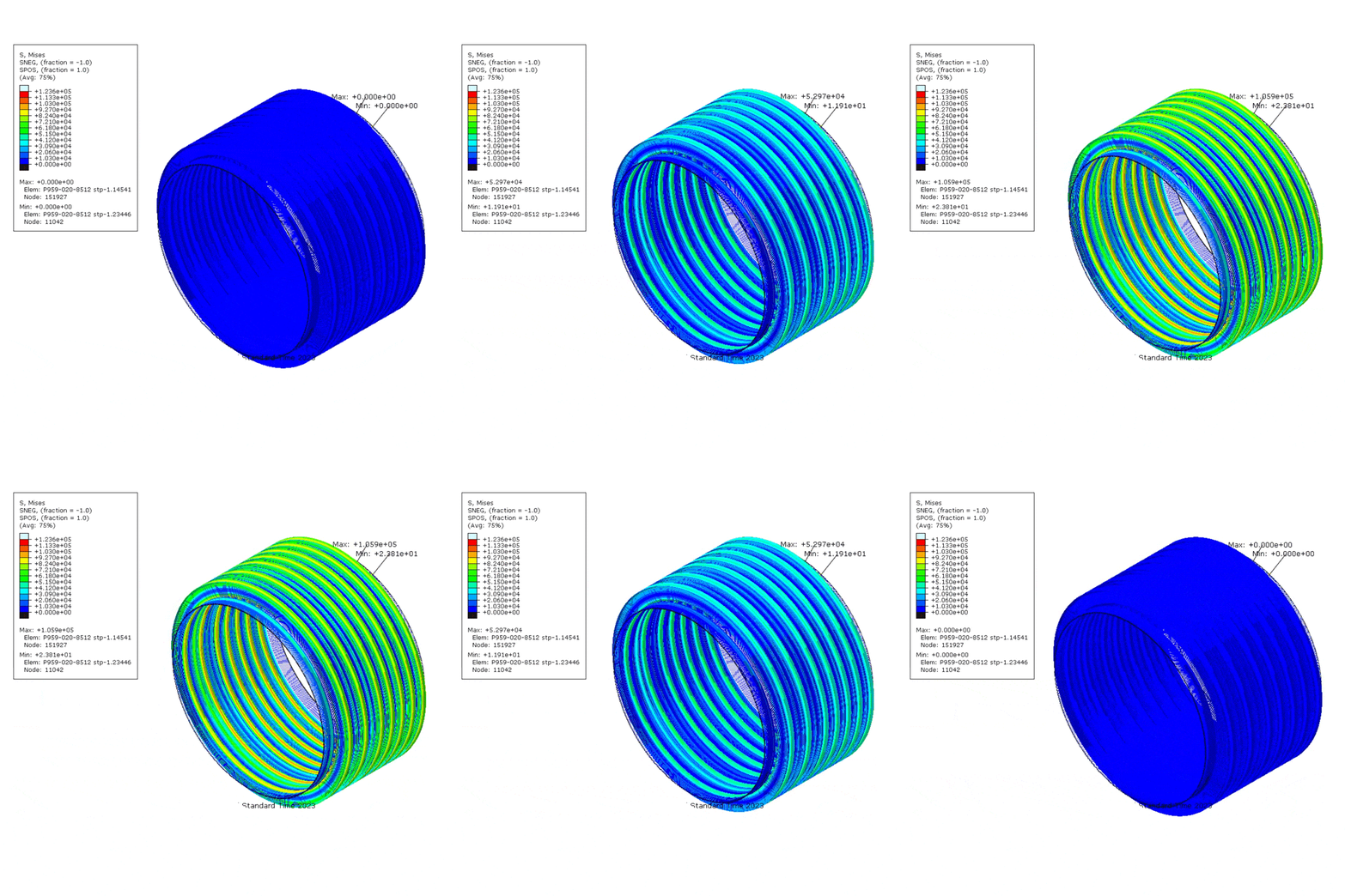
AXIAL COMPRESSION
image

The dimensional shortening of a pipe expansion joint along its longitudinal axis. Axial compression may been referred to as axial movement, traverse or compression.

AXIAL EXTENSION

The dimensional lengthening of a pipe expansion joint along its longitudinal axis. Axial extension may been referred to as axial movement, traverse or compression.

ANCHOR, DIRECTIONAL

A directional or sliding anchor, is one which is designed to absorb loading in one direction while permitting motion in another. It may be either a main or intermediate anchor, depending upon the application involved. When designed for this purpose, a directional anchor may also function as a pipe alignment guide. In the design of a directional anchor, an effort should be made to minimize the friction between its moving or sliding parts, since this will reduce the loading on the piping and equipment and insure proper functioning of the anchor.

ANCHOR, MAIN

A main anchor is one which must withstand the full bellows thrust due to pressure, flow, spring forces, etc.

ANCHOR, INTERMEDIATE

An intermediate anchor is one which must withstand the bellows thrust due to flow, spring forces, etc., but not the thrust due to pressure.

BELLOWS

The flexible element of a pipe expansion joint consisting of one or more convolutions and the end tangents, if any.

CONTROL RODS

Devices, usually in the form of rods or bars, attached to the pipe expansion joint assembly whose primary function is to distribute movement between the two bellows of a universal pipe expansion joint. Control rods are not designed to restrain pressure thrusts.

CONVOLUTION
The smallest flexible unit of a bellows. The total movement capacity of a bellows is proportional to the number of convolutions.
COVER
A device used to provide limited protection of the exterior surface of the bellows of a pipe expansion joint from foreign objects or mechanical damage. A cover is sometimes referred to as a shroud
EJMA
Expansion Joint Manufacturers Association. is an organization of established manufacturers of metal bellows type expansion joints. EJMA set standards in manufacturing a metal bellow or expansion joints.EJMA Standards are recognized throughout the world as the authority on the proper selection and application of metallic bellows type expansion joints for safe and reliable piping and vessel installation
DOUBLE PIPE EXPANSION JOINTS
A double pipe expansion joint consists of two bellows joined by a common connector which is anchored to some rigid part on the installation by means of an anchor base. The anchor base may be attached to the common connector either at installation or at time of manufacture. Each bellows acts as a single pipe expansion joint and absorbs the movement of the pipe section in which it is installed, independently of the other bellows. Double pipe expansion joints should not be confused with universal pipe expansion joints.
EQUALIZING AND REINFORCING RINGS
Devices used on some pipe expansion joints fitting snugly in the roots of the convolutions. The primary purpose of these devices is to reinforce the bellows against internal pressure. Equalizing rings are made of cast iron, carbon steel, stainless steel or other suitable alloys and are approximately “T” shaped in cross section. Reinforcing rings are fabricated from tubing or solid round bars of carbon steel, stainless steel, or other suitable alloys.
PIPE EXPANSION JOINTS
Any device containing one or more bellows used to absorb dimensional changes, such as those caused by thermal expansion or contraction of a pipeline, duct, or vessel. 
FLANGED ENDS
The ends of a pipe expansion joint equipped with flanges for the purpose of bolting the pipe expansion joint to the mating flanges of adjacent equipment or piping.
GIMBAL PIPE EXPANSION JOINTS
A gimbal pipe expansion joint is designed to permit angular rotation in any plane by the use of two pairs of hinges affixed to a common floating gimbal ring. The gimbal ring, hinges and pins must be designed to restrain the thrust of the pipe expansion joint due to internal pressure and extraneous forces, where applicable.
HINGED PIPE EXPANSION JOINT
A hinged pipe expansion joint contains one bellows and is designed to permit angular rotation in one plane only, by the use of a pair of pins through hinge plates attached to the pipe expansion joint ends. The hinges and hinge pins must be designed to restrain the thrust of the pipe expansion joint due to internal pressure and extraneous forces, where applicable. Hinged pipe expansion joints should be used in sets of two or three to function properly.
IN-LINE PRESSURE BALANCED PIPEEXPANSION JOINT
An in-line pressure balanced pipe expansion joint is designed to absorb axial movement and/or lateral deflection which is restraining the pressure thrust by means of tie devices interconnecting the line bellows with outboard compensating bellows also subjected to line pressure. Each bellow set is designed to absorb the axial movement and usually the line bellows will absorb the lateral deflection. This type of pipe expansion joint is used in a straight run of piping.
INTERNAL LINER
A device which minimizes contact between the inner surface of the bellows of a pipe expansion joint and the fluid flowing through it. These devices have also been referred to as liners, telescoping sleeves, etc. .
INTERNALLY GUIDED PIPE EXPANSION JOINT
An internally guided pipe expansion joint is designed to provide axial guiding within the pipe expansion joint by incorporating a heavy internal guide sleeve, with or without the use of bearing rings. The use of such pipe expansion joints will assure installation without initial lateral or angular misalignment and can be installed in pipelines where reverse flow will be encountered. NOTE: The use of an internally guided pipe expansion joint does not eliminate the necessity of using adequate external pipe guides.
LATERAL DEFLECTION
The relative displacement of the two ends of a pipe expansion joint perpendicular to its longitudinal axis. This has been referred to as lateral offset, lateral movement, parallel misalignment, direct shear or transverse movement. .
LIMIT RODS
Devices, usually in the form of rods or bars, attached to the pipe expansion joint assembly whose primary function is to restrict the bellows movement range (axial, lateral and angular) during normal operation. They are designed to prevent over-extension or over-compression of the bellows while restraining the full pressure loading and dynamic forces generated by a main anchor failure. .
MOTION INDICATORS
Devices, usually in the form of rods or bars, attached to the pipe expansion joint assembly whose primary function is to restrict the bellows movement range (axial, lateral and angular) during normal operation. They are designed to prevent over-extension or over-compression of the bellows while restraining the full pressure loading and dynamic forces generated by a main anchor failure. Another common example of motion indicators is found on slotted hinge assemblies. With the hinge pin used as an indicator, permanent marks are scribed upon the hinge hardware to record the original cold position. The relative distance between the pin and the cold position mark can then be used to determine the movements imposed upon the bellows.
PANTOGRAPH LINKAGES
A scissor-like device. A special form of control rod attached to the pipe expansion joint assembly whose primary function is to positively distribute the movement equally between the two bellows of the universal joint throughout its full range of movement. Pantograph linkages, like control rods, are not designed to restrain pressure thrusts.
PIPE ALIGNMENT GUIDE
A pipe alignment guide is a form of framework fastened to some rigid part of the installation which permits the pipeline to move freely along the axis of the pipe. Pipe alignment guides are designed primarily for use in applications involving lateral deflection and angular rotation.
PIPE SECTION
A pipe section is that portion of a pipeline between two anchors. All dimensional changes in a pipe section must be absorbed between these two anchors.
PLANAR PIPE GUIDE
A planar pipe guide is one which permits transverse movement and/or bending of the pipeline in one plane. It is commonly used in applications involving lateral deflection or angular rotation resulting from “L” or “Z” shaped piping configurations.
PRESSURE BALANCED PIPE EXPANSION JOINT
A pressure balanced expansion pipe joint is designed to absorb axial movement and/or lateral deflection while restraining the pressure thrust by means of tie devices interconnecting the flow bellows with an opposed bellows also subjected to line pressure. This type of pipe expansion joint is normally used where a change of direction occurs in a run of piping but can be designed as an in-line device where no change of direction is necessary. The flow end of a pressure balanced pipe expansion joint sometimes contains two bellows separated by a common connector, in which case it is called a universal pressure balanced pipe expansion joint.
PURGE CONNECTIONS
Purge connections, where required, are usually installed at the sealed end of each internal sleeve of a pipe expansion joint for the purpose of injecting a liquid or gas between the bellows and the internal sleeve to keep the area clear of erosive and corrosive media and/or solids that could pack the convolutions. Purging may be continuous, intermittent or just on start-up or shut down, as required. These are sometimes called aeration connections.
RATED MOVEMENT
The maximum amount of movement (axial extension, axial compression, lateral deflection, angular rotation, or any combination thereof) which a pipe expansion joint is capable of absorbing. This rating may be different for each size, type and making of pipe expansion joint and is established by the manufacturer.
SHIPPING DEVICES
Rigid support devices installed on a pipe expansion joint to maintain the overall length of the assembly for shipment. These devices may also be used to pre-compress, pre-extend or laterally offset the bellows.
SINGLE PIPE EXPANSION JOINT
The simplest form of pipe expansion joint, of single bellows construction, designed to absorb all of the movements of the pipe section in which it is installed.
SWING PIPE EXPANSION JOINT
A swing pipe expansion joint is designed to absorb lateral deflection and/or angular rotation in one plane. Pressure thrust and extraneous forces are restrained by the use of a pair of swing bars, each of which is pinned to the pipe expansion joint ends.
TANGENTS
The straight unconvoluted portions at the end of the bellows.
TIE RODS
Devices, usually in the form of rods or bars, attached to the pipe expansion joint assembly whose primary function is to continuously restrain the full pressure thrust during normal operation while permitting only lateral deflection. Angular rotation can be accommodated only if two tie rods are used and located 90 degrees opposed to the direction of rotation.
UNIVERSAL PIPE EXPANSION JOINT
A universal pipe expansion joint is one containing two bellows joined by a common connector for the purpose of absorbing any combination of the three basic movements, i.e. axial movements, lateral deflection and angular rotation. Universal pipe expansion joints are usually furnished with control rods to distribute the movement between the two bellows of the pipe expansion joint and stabilize the common connector. This definition does not imply that only a universal pipe expansion joint can absorb combined movements.
WELD ENDS
The ends of a pipe expansion joint equipped with pipe suitably beveled for welding to adjacent equipment or piping.
TURBOCHARGERS
A turbocharger is a turbine-driven forced induction device that increases an internal combustion engine’s efficiency and power output by forcing extra air into the combustion chamber. This improvement over a naturally aspirated engine’s power output is due to the fact that the compressor can force more air and proportionately more fuel into the combustion chamber than atmospheric pressure alone.